Beam-Tracking Challenges in THz Communications
Giorgos Stratidakis, Sotiris Droulias and Angeliki Alexiou*
Department of Digital Systems, University of Piraeus, Piraeus 18534, Athens, Greece
E-mail: giostrat@unipi.gr; sdroulias@unipi.gr; alexiou@unipi.gr
*Corresponding Author
Manuscript received 06 August 2023, accepted 02 January 2024, and ready for publication 21 March 2024.
© 2024 River Publishers
In recent years, the demand for high data rates has increased drastically. In response to this increasing demand, higher frequencies, such as millimeter wave (mmWave) and terahertz (THz) have been considered that offer much larger bandwidth and potentially much higher data rates. Nevertheless, with the increase in frequency, the pathloss increases significantly, with the non-line-of-sight (nLoS) incurring attenuation levels that can dramatically reduce the quality of a wireless link. The use of directional antennas to counteract the increased pathloss is widely accepted. However, highly directional beams are prone to misalignment and a method to track the tracking object (TO) of the link with consistency, accuracy and low overhead is needed. To this end, the design of beam-tracking algorithms has been proposed. In this work, the main parameters that affect the reliability of beam-tracking are presented along with the challenges that beam-tracking algorithms need to address. Furthermore, the performance merits with respect to three reliability parameters are presented in the case of a simple beam-tracking algorithm.
Keywords: Beam-forming, beam-tracking, reliability, terahertz.
For a link to be established with directional antennas, they must be properly aligned or the received power will be reduced which can lead to outage [1, 2, 3]. If both the transmitter (TX) and receiver (RX) are static, the alignment of their antennas is simple as it can be done once and make corrective actions to fix any future misalignment (caused by earthquakes, wind, etc). On the other hand, if either the TX or RX is mobile, and at least one of them is equipped with a directional antenna, the one with directional antenna requires a method to track the direction of the other part of the link in order to properly align the beam (or beams). This can be realized with either localization or beam-training/tracking. Localization, beam-training and tracking must be highly accurate for the misalignment to be low and the received power high. The accuracy threshold is dependent on the half-power beamwidth (HPBW) of the beams and is not universal. For example, a localization or beam-training/tracking error that leads to a directional error of can be acceptable with an HPBW of but not with an HPBW of . In other words, the narrower the HPBW the lower the acceptable directional error. Depending on the scenario, localization may require additional equipment (e.g. sensors) and is not always accurate enough by itself. Beam-training offers high reliability at the cost of increased overhead. Beam-tracking aims to offer the same reliability with beam-training but with reduced overhead [4, 5]. To do this a prediction is used, which requires a number of pre-acquired samples to begin. These samples are acquired through beam-training or localization. The accuracy of the prediction depends on the trajectory type of the user equipment (UE) motion in relation to the access point (AP) location. The direction of the UE motion affects the perception of the directional/angular variations relative to the tracker. For example, there are no angular variations if the UE moves towards the tracker in a straight line. The speed and AP-UE distance are closely related as the closer the UE is to the AP the faster it appears to move for this AP and vice versa. The trajectory of the UE directly affects the accuracy of the prediction as any abrupt changes in direction can make the prediction fail. Furthermore, the sampling rate of the trajectory by the tracker affects the mapping resolution of the trajectory, which in turn affects the prediction accuracy. For example, with low sampling rate the mapped trajectory resembles random points in the area. With high sampling rate, the mapped trajectory begins to resemble the actual trajectory. With very high sampling rate and assuming there are no estimation errors, the mapped and actual trajectories are identical. However, with increased sampling rate comes an increased tracking overhead that decreases the data transmission time. Finally, blockage can disrupt communication [6, 7], and therefore the beam-tracking process and make the prediction fail as it creates blanks in the mapped trajectory.
In this work, the parameters that affect the beam-tracking reliability are identified, including the obvious ones such as the UE motion, the area geometry, tracking orientation frequency and some less obvious such as the antenna orientation of the UE. Furthermore, a simple beam-tracking algorithm is introduced, along with some simple solutions that counteract the randomness of the angular variations of the user’s motion. Finally, the performance of the presented solutions is presented and compared through simulations.
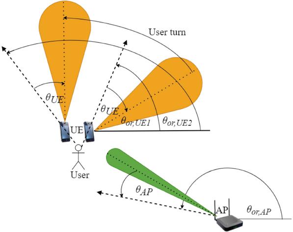
In this work a typical THz massive multiple-input multiple-output (MIMO) system is considered, with one tracker and one TO as shown in Figure 1. The tracker is equipped with a directional antenna of antenna elements, and the TO with an omnidirectional antenna. Assuming that there is no blockage, the baseband equivalent received signal vector for the TO can be obtained as
| (1) |
where , and stand for the MIMO channel vector, the codebook matrix and the digital precoding vector. Moreover, denotes the transmitted signal vector with normalized power, and indicates the additive Gaussian noise (AWGN) vector. In this work, the Saleh-Valenzuela channel model is adopted [8]. In THz frequencies scattering induces more than dB attenuation in the nLoS components [9], and therefore only the LoS component is taken into account, which is multiplicative to the array steering vector
| (2) |
where . The spatial direction can be calculated as , where is the actual direction of the TO, is the spacing between the antenna elements, and is the wavelength. It is assumed that .
Figure 1 System model of an indoor scenario with AP, and UE. The dashed lines depict the orientation of the AP and UE antennas. The straight solid lines depict the horizontal axis from which the orientation angles and are estimated. The angles and are the angles that the beam-tracking process attempts to estimate. As the user turns the antenna orientation of the UE changes from to . Therefore the direction of the beam changes but the angle stays the same.
A widely used generic frame structure for THz communications consists of multiple timeslots, the first of which are occupied by the beam-racking and channel estimation procedures, followed by the data transmission [10]. The beam-tracking timeslot includes the entire beam-tracking process, such as coarse beam-tracking and angle estimation phases [11], or beam-tracking and localization [12]. The frame begins with the beam-tracking procedure to find the direction of the TO, which is followed by the channel estimation in the direction estimated by the tracking process and then the data transmission. The duration of beam-tracking must be shorter than the duration of the data transmission for the beam-tracking efficiency to be high.
The parameters that affect the reliability of beam-tracking can be divided into two main categories, the ones that affect the trajectory mapping resolution, and the ones that affect the angular resolution as shown in Figure 2. Specifically, the trajectory mapping resolution refers to the successful tracking of the trajectory (either location or angular) of the UE motion, which is affected by the prediction of the location/direction of the TO by the tracker, and the angular scanning area. The accuracy of the prediction is affected by the angular variation of the UE motion, the prediction algorithm and the tracking estimation frequency. The angular variation expresses how fast the direction of the TO changes in relation to the position of the tracker and the tracking estimation frequency, expresses how often the tracking process is performed. The angular variation is the result of the UE motion (speed, direction, and trajectory type), in relation to the location of the AP, i.e. the point of view (POV) of the AP (see Figure 3) if the AP is tracking the UE, and the direction of the UE motion. In the case of the UE tracking the AP, the point of view of the UE is affected greatly by the antenna orientation of the UE which changes along with the direction of the UE motion. Furthermore, the UE motion can be limited by the environment and in particular the area geometry. For example, the UE motion is more limited in a narrow corridor than in an open area such as a mall. The limited motion in a corridor, along with the appropriate placement of the AP translates to small angular variation and as a result, small prediction errors, which are easy to compensate for. The trajectory type refers to UE moving in a linear way, or a more complex way with fast direction changes (or trajectory variation) as shown in Figure 4(a). As expected, the trajectory type of the UE motion affects the angular variations in a direct way as shown in Figure 4(b) and (c), where the angular variation from the point of view of a static and a mobile tracker is presented. If the UE uses a location prediction for the location of the AP, the changes in the antenna orientation of the UE must be known to the UE. The tracking estimation frequency affects the continuity of the trajectory that is perceived by the tracker and the detected angular variations. In other words, it is the sampling rate of the trajectory/direction. The angular scanning area refers to area that is searched by the tracker and is the result of the antenna beamwidth of the tracker and the number of pilots that are sent to find the TO. Angular resolution refers to the number of directions that are successfully scanned and it is affected by the angular scanning area, and blockage. Blockage occurs when an object or human is between the tracker and the TO, and can obstruct the scanning of specific directions. The motion of the blocking object/human is independent of the AP and the UE, but like them is restricted by the area geometry.
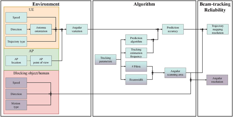
Figure 2 Tracking reliability parameters. The parameters are divided to two main categories, the ones that affect the trajectory tracking resolution and the ones that affect the angular resolution. The dashed boxes, “Antenna orientation”, and “AP point of view” are only relevant when the AP is tracking the UE and when the UE is tracking the AP, respectively. The symbol # in Pilots denotes the number of pilots.
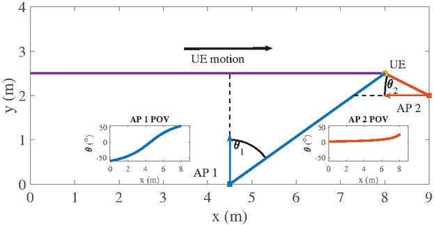
Figure 3 AP/Tracker location point of view with regards to the UE motion. The colored arrows denote the antenna orientation of each AP and the black colored arrow denotes the general direction of the UE motion. In the insets, the angular variation of the UE motions from the different point of views of AP and is shown.
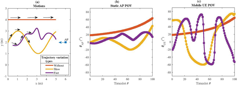
Figure 4 Trajectory variation types of a UE motion, with a static AP. (a) Variation types, (b) angular variation from the point of view of a static tracker (AP), and (c) angular variation from the point of view of a mobile tracker (UE). The antenna orientation of the AP is depicted with the blue arrow, and the antenna orientation of the UE changes with the motion and is depicted with the black arrows for each motion. It is assumed that there is no blockage. The markers in panels (b) and (c) show how sudden the changes in direction are.
There are many challenges in tracking a mobile UE, the most obvious of which is the motion of the UE, which can be broken down to speed, direction and type of trajectory (linear, irregular, etc). In Figure 4(a), three motions are presented with different trajectory variation types (without, slow and fast), and their angular variation from the point of view of the AP and the UE is shown in Figure 4(b) and (c). It can be observed that different trajectories have different angular variation in relation to the a single AP. For ease of reference, the trajectory without variation will be named “Trajectory 1”, the trajectory with slow variation “Trajectory 2” and the trajectory with fast variation “Trajectory 3”. Trajectory 1 is linear and the angular variation it causes in relation to the AP location is slow. Trajectory 2 is sinusoidal and the angular variation it causes is faster. Trajectory 3 is a random trajectory and causes slow angular variation at the start and faster towards the end. Furthermore, it has more changes in direction than the Trajectory 2. Both Trajectory 2 and 3 are harder to follow than Trajectory 1. The main parameter that affects the performance of beam-tracking is the beamwidth. Wide beams cover a relatively large area and therefore make tracking easier, but with low accuracy and antenna gain. On the other hand, narrow beams cover a smaller area making tracking harder but with increased accuracy and antenna gain. In the case where the UE tracks the AP, the direction of the UE motion is especially important as in most cases it affects the antenna orientation of the UE, and any changes to it significantly affect the angular variation, as shown in Figure 4(c), which can impair the beam-tracking performance. If a direction prediction is used, the antenna orientation changes are included in the prediction. However, if the UE uses a location-based prediction, then the antenna orientation of the UE must be known for the UE to form a beam in the direction of the AP. For example, the UE antenna forms a beam at right of the broadside to the direction of the AP. The user then turns left and the direction of the UE beam stops pointing to the direction of the AP and the link is broken (see for example Figure 1). In order to restore the link, the UE antenna must form a beam to the right. This can happen even with static user. There are methods that allow the UE to know the direction changes and in turn the antenna orientation changes, such as using a gyroscope, [13], or the camera of a smartphone [14]. Using the camera however, raises privacy concerns. Another factor that greatly affects beam-tracking is blockage and particularly human blockage, since objects are mostly static. Blockage can significantly impede beam-tracking, especially when combined with highly directional beams as the probability of a link being blocked completely (total blockage) instead of partially increases with narrower beams. Moreover, user-blockage makes the area behind the user non-scannable. One method to cope with blocked links is to scan around the presumed blocker and wait for the blockage to end [10], assuming the duration is short.
The use of multiple APs, relays and RISs is the most obvious solution to avoid blocked links [15]. Self-healing is another promising solution to blockage as it allows for the beam to regenerate behind the obstacle [16]. This way the required number of APs, relays and RISs can be reduced significantly and in the best case scenario only AP (per room if indoors) will be required.
In this section a simple beam-tracking algorithm is presented for the purpose of explaining the required steps in a beam-tracking process. It is assumed that the beam-tracking is performed by the AP. In general, a beam-tracking algorithm consists of an initialization phase, in which the necessary input is obtained (e.g. some direction/location estimations) and the beam-tracking phase that consists of the prediction and the tracking in a small amount of directions around the predicted direction. Other phases, such as a correction phase can be added if necessary. In general, the initialization phase includes an exhaustive search. In this paper, the initialization phase lasts for timeslots, where the tracker estimates the direction of the UE with exhaustive search using the hierarchical codebook. Specifically, binary search is used and reduces total number of pilots required for the exhaustive search to . Note that the codewords of the first codebook level can be skipped in favor of using codewords in the second level, for the increased antenna gain without increasing the pilot overhead. After the initialization phase, the tracker starts predicting the next direction of the UE relative the position of the tracker. The prediction assumes that the angular variation of the UE motion relative to the position of the tracker in two timeslots is consistent (i.e. the trajectory is circular). The simplicity of the prediction allows for the accurate assessment of other methods in increasing the tracking reliability.
In this section some simulation results with reliability increase methods are presented. Unless otherwise stated, the central frequency is GHz, and the number of antenna elements of the AP is . It is assumed that the number of active antenna elements follows , where is the codebook level used and is the last codebook level, in this case . Furthermore, the codebook in [17] is used. The antenna element spacing is , the initialization phase lasts timeslots as it was mentioned in Section 6, and the number of pilots used in the beam-tracking process is . The number of pilots required by the initialization phase is and serves as a benchmark. The number of pilots required by the beam-tracking process to fully track a trajectory can be estimated as , where is the number of pilots per timeslot, is the number of timeslots in which the beam-tracking process is performed and is the number of timeslots in which the initialization is performed, which in this work is . The antenna of the UE is assumed to be omni-directional. The beam-tracking process does not take corrective measures are taken when it fails to find the UE, in order to make the performance assessment easier. In this work, all trajectories are divided in parts, the start of each one representing a sample taken with the beam-tracking process in timeslot, for a total of samples and timeslots of beam-tracking. The estimation frequency, , is a multiplicative factor in the number of samples. For example, when , samples are taken from the trajectory in timeslots, when , samples in timeslots, etc.
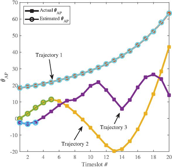
Figure 5 Beam-tracking example from the point of view of the AP for the trajectories shown in Figure 4. The beam-tracking process is successful in Trajectory 1 due to the slow angular variation, but fails in Trajectories 2 and 3 due to the fast angular variation.
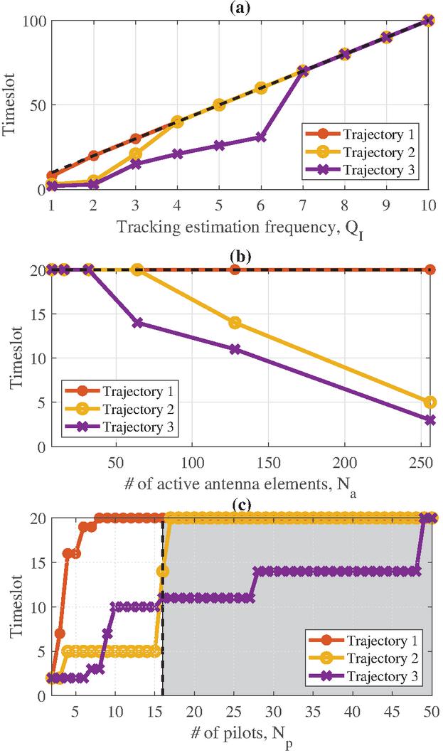
Figure 6 Performance of the reliability increase methods. (a) Tracking estimation frequency, (b) number of active antenna elements, and (c) number of pilots vs the last timeslot in which the beam-tracking process succeeded. In (a) and (b), the dashed line depicts the maximum number of timeslots for the beam-tracking process. In (c), the dashed line at pilots marks the number of pilots used in the initialization and acts as a benchmark.
In Figure 5, an example of beam-tracking from the point of view of the AP for the three trajectories shown in Figure 4, namely Trajectory 1, Trajectory 2 and Trajectory 3 is presented. The tracking estimation frequency, , the maximum number of active antenna elements is and the number of pilots (i.e. the number of directions that can be scanned) used in the beam-tracking process is . Trajectory 1 can be fully tracked due to the slow angular variation, however the beam-tracking process in Trajectories 2 and 3 fails at the start due to the fast angular variation. In order to track the Trajectories 2 and 3 entirely, the accuracy of the prediction algorithm must increase. To do this without changing the prediction algorithm, the angular variation between two consecutive timeslots must become slower and the scanning area of the tracker must be increased. The angular variation can become slower by increasing the tracking estimation frequency, . By increasing , the distance travelled by the UE between two consecutive timeslots decreases and so does the angular variation that is perceived by the AP. To increase the scanning area of the tracker, the number of directions to scan (and therefore the number of pilots sent by the AP, ) must be increased, or the beamwidth of the AP antenna must be increased by reducing the number of active antenna elements, . Although the above-mentioned methods have the potential to fully track the UE trajectories, the requirements to do so are different for each method. Furthermore, higher requirements mean higher overhead. The trade-off between the beam-tracking reliability and the overhead that is required to achieve it is the focus of most works on beam-tracking. In Figure 6, the last timeslot in which the beam-tracking process successfully found the UE is presented as a function of (a) , (b) the number of active antenna elements, and c), the number of pilots used in tracking, for all trajectories shown in Figure 4. Unless otherwise stated, the tracking estimation frequency , the number of pilots and the number of active antenna elements is . It is observed that increasing the tracking estimation frequency in (a), increases the number of timeslots in which the UE is successfully tracked. As expected, the tracking of the entire Trajectory 1 is successful from and for , only a small part of the trajectory is not tracked. However, as the angular variation speed of the trajectory becomes faster, tracking the entire trajectory becomes more difficult. For Trajectory 2 and 3, the tracking of the entire trajectory is achieved with and , respectively. Further increase of increases the pilot overhead without increasing the performance. For a specific trajectory, the increase is not linear due to the changes in the angular variation from the point of view of the AP. For example, the angular variation of Trajectory 2 becomes faster as the UE moves towards the AP. In (b), increasing the number of active elements while using the same number of pilots decreases the scanning area due to the narrower beams and can decrease the probability of tracking the UE. Again, Trajectory 1 is always entirely tracked, while for Trajectory 2 and Trajectory 3, increasing the number of active antenna elements reduces the number of timeslots that can be tracked. Trajectory 1 can be tracked with all antenna elements, while Trajectories 2 and 3 can be tracked with and antenna elements respectively. In (c), increasing the number of pilots increases the number of timeslots of successfully tracking the UE due to the larger scanning area. The increase is not linear as the prediction is not accurate enough and a larger scanning area is required. For example, Trajectory 1 requires pilots, Trajectory 2 requires to be entirely tracked and Trajectory 3 requires pilots. As the angular variation of Trajectory 2 at the start is slower than the angular variation of Trajectory 3, it can be tracked with fewer pilots. However, as both trajectories progress, the speed of their angular variation changes. In the next part of both trajectories, the angular variation of Trajectory 3 is slower than that of Trajectory 2 and therefore Trajectory 3 can be tracked up to this point with fewer pilots than Trajectory 2. Overall, the angular variation of Trajectory 2 is slower than that of Trajectory 3 and therefore can be tracked with fewer pilots. It should be noted that increasing the number of pilots to and higher is inefficient as the initialization requires pilots and is more probable to find the UE due to using the binary search method, which is a version of the exhaustive search. It is observed that all solutions can help the AP track the 3 trajectories entirely, but with different cost, e.g. pilot overhead. For example, the total number of pilots, excluding the initialization phase, without using a reliability increase method is , with increasing to in (a) it is , with reducing to in (b) it is , and with increasing to in (c) it is . In this case, the increased performance relative to the pilot overhead of reducing seems to be the best among the presented solutions but the reduced gain that follows can reduce the viability of the solution in cases where high antenna gain or high accuracy is required. Increasing the number of pilots seems to be the worst solution as the pilot overhead required for the AP to track all trajectories is the highest. Increasing is the middle ground between increasing and decreasing in the beam-tracking process. It requires significantly fewer pilots than increasing to fully track all UE trajectories and without decreasing the antenna gain. Although, all solutions can fully track the UE trajectories, the optimal solution depends on the scenario. If high gain or high accuracy is required, then increasing the tracking estimation frequency is the best solution among the three. On the other hand, if the antenna gain or accuracy requirements are not high, then increasing the beamwidth by decreasing the number of active antenna elements is the best solution between the three. Increasing the number of pilots is preferred only if it is lower than the number of pilots required by the initialization. Note that a more accurate prediction will significantly increase the performance of beam-tracking with low overhead, especially if used in conjunction with one of the above-mentioned methods.
One simple way of decreasing the number of pilots without decreasing the scanning area is by making use of the codebook. Specifically, with the use of multiple codebook levels instead of only the last one, the pilot overhead can be reduced substantially by taking advantage of the binary tree structure of the codebook and the binary search method. For example, instead of using pilots in the last codebook level, the same scanning area can be achieved with using pilots in the codebook level and pilots in the last level for a total of pilots, which is a decrease.
This paper provides an overview on beam-tracking methods for finding the direction of the user. The parameters that affect the reliability of beam-tracking algorithms were identified, and divided into two main categories, the trajectory mapping resolution and the angular resolution. Trajectory mapping resolution was defined as the successful tracking of the UE over time and the angular resolution the number of directions that can be successfully scanned each time. In contrast to localization, beam-tracking aims to offer greater accuracy and with lower overhead than beam-training. However, the accuracy of beam-tracking is related to the accuracy of the prediction and the scanning area. The accuracy of a prediction algorithm can be increased by increasing the tracking estimation frequency. The scanning area can be increased by decreasing the number of active antenna elements to form wider beams or by increasing the number of pilots sent by the tracker. These 3 methods were presented and compared with each other in terms of performance, overhead and requirements, to find how much they affect tracking and the cost that comes with them. It was shown that greatly increasing the scanning area by increasing the number of pilots to high levels is not a viable solution due to the high pilot overhead, although finding the ideal number of pilots for the UE trajectory is vital. Furthermore, increasing the beamwidth by decreasing the number of active antenna elements increases the tracking reliability, but also decreases the antenna gain which can undesirable at mmWave and THz frequencies. Increasing the tracking estimation frequency was observed to be a good solution as it increases the accuracy of the prediction and therefore the tracking reliability with relatively low increase of the pilot overhead. The tracking reliability can be significantly improved with a more accurate prediction algorithm. Furthermore, the addition of more APs, relays and RISs can increase the tracking reliability in cases of blockage, if at least AP-UE link is LoS. The cost however (e.g. total pilot overhead) can increase significantly.
This work was supported by the European Commission’s Horizon Europe Programme under the Smart Networks and Services Joint Undertaking (TERA6G project Grant Agreement 101096949).
[1] S. Priebe, M. Jacob, and T. Kürner, “The impact of antenna directivities on THz indoor channel characteristics,” in 2012 6th European Conference on Antennas and Propagation (EUCAP), pp. 478–482, 2012.
[2] E. N. Papasotiriou, A.-A. A. Boulogeorgos, and A. Alexiou, “Performance Analysis of THz Wireless Systems in the Presence of Antenna Misalignment and Phase Noise,” IEEE Commun. Lett., pp. 1–1, 2020.
[3] A.-A. A. Boulogeorgos, E. N. Papasotiriou, and A. Alexiou, “Analytical Performance Assessment of THz Wireless Systems,” IEEE Access, vol. 7, no. 1, pp. 1–18, Jan. 2019.
[4] Y. Wang, Z. Wei, and Z. Feng, “Beam Training and Tracking in MmWave Communication: A Survey,” 2022.
[5] B. Ning, Z. Chen, Z. Tian, C. Han, and S. Li, ‘‘A Unified 3D Beam Training and Tracking Procedure for Terahertz Communication,” IEEE Transactions on Wireless Communications, vol. 21, no. 4, pp. 2445–2461, 2022.
[6] G. R. MacCartney, S. Deng, S. Sun, and T. S. Rappaport, “Millimeter-Wave Human Blockage at 73 GHz with a Simple Double Knife-Edge Diffraction Model and Extension for Directional Antennas,” in IEEE 84th Vehicular Technology Conference (VTC-Fall), IEEE, Sep 2016.
[7] M. Jacob, S. Priebe, R. Dickhoff, T. Kleine-Ostmann, T. Schrader, and T. Kurner, “Diffraction in mm and Sub-mm Wave Indoor Propagation Channels,” IEEE Transactions on Microwave Theory and Techniques, vol. 60, no. 3, pp. 833–844, Mar 2012.
[8] A. Saleh and R. Valenzuela, “A Statistical Model for Indoor Multipath Propagation,” IEEE Journal on Selected Areas in Communications, vol. 5, no. 2, pp. 128–137, 1987.
[9] E. N. Papasotiriou, J. Kokkoniemi, A.-A. A. Boulogeorgos, J. Lehtomaki, A. Alexiou, and M. Juntti, ‘‘A new look to 275 to 400 GHz band: Channel model and performance evaluation,” in IEEE 29th Annual International Symposium on Personal, Indoor and Mobile Radio Communications (PIMRC), IEEE, Sep. 2018.
[10] J. Tan and L. Dai, “Wideband Beam Tracking in THz Massive MIMO Systems,” IEEE Journal on Selected Areas in Communications, vol. 39, no. 6, pp. 1693–1710, 2021.
[11] S. Kim, G. Kwon, and H. Park, “High-resolution multi-beam tracking with low overhead for mmWave beamforming system,” ICT Express, vol. 7, no. 1, pp. 28–35, 2021.
[12] G. Stratidakis, A.-A. A. Boulogeorgos, and A. Alexiou, “A cooperative localization-aided tracking algorithm for THz wireless systems,” in IEEE Wireless Communications and Networking Conference (WCNC), Marrakech, Morocco, Apr. 2019.
[13] S. Yean, B. S. Lee, C. K. Yeo, C. H. Vun, and H. L. Oh, “Smartphone Orientation Estimation Algorithm Combining Kalman Filter With Gradient Descent,” IEEE Journal of Biomedical and Health Informatics, vol. 22, no. 5, pp. 1421–1433, 2018.
[14] W. Elloumi, K. Guissous, A. Chetouani, R. Canals, R. Leconge, B. Emile, and S. Treuillet, “Indoor navigation assistance with a Smartphone camera based on vanishing points,” in International Conference on Indoor Positioning and Indoor Navigation, pp. 1–9, 2013.
[15] G. Stratidakis, S. Droulias, and A. Alexiou, “A beam-tracking framework for THz networks,” Frontiers in Communications and Networks, vol. 3, 2022.
[16] P. Zhou, X. Fang, Y. Fang, R. He, Y. Long, and G. Huang, “Beam Management and Self-Healing for mmWave UAV Mesh Networks,” IEEE Transactions on Vehicular Technology, vol. 68, no. 2, pp. 1718–1732, 2019.
[17] Z. Xiao, T. He, P. Xia, and X. Xia, “Hierarchical Codebook Design for Beamforming Training in Millimeter-Wave Communication,” IEEE Trans. Wireless Commun., vol. 15, no. 5, pp. 3380–3392, May 2016.

Giorgos Stratidakis was born in Athens, Greece, in 1990. He received the bachelor’s degree in telecommunications engineering from the Department of Telecommunications Science and Technology, University of Peloponnese, in 2016, and the master’s degree in digital communications and networks from the Department of Digital Systems, University of Piraeus, in 2018. He is currently pursuing the Ph.D. degree in wireless communications. In 2017, he joined the Department of Digital Systems, University of Piraeus, where he conducts research in the area of wireless communications.

Sotiris Droulias received the diploma in electrical and computer engineering and the Ph.D. degree in nonlinear photonics from the National Technical University of Athens, Athens, Greece, in 2001 and 2007, respectively. He is currently a Research Associate at the Department of Digital Systems, ICT School, University of Piraeus, Piraeus, Greece. During the period 2012–2020 he was a member of the Photonic- Phononic- and Meta-materials group at FORTH-IESL, Crete, Greece, and during the period 2009–2012 we worked as an Adjunct Lecturer at the University of Patras. He has worked on several EC funded projects and his research interests include metamaterials, photonic crystals, metasurfaces, nanolasers, plasmonics, active media. He is an author of more than 30 papers and 2 book chapters, he has received more than 15 talk invitations in prestigious conferences and he serves as a reviewer in several scientific journals. In 2019 he received the best poster award for his work on metasurface lasers in META 2019, Lisbon, Portugal, and in 2020 he was recognized as an outstanding reviewer from the Institute of Physics (IOP).

Angeliki Alexiou is a professor at the department of Digital Systems, ICT School, University of Piraeus. She received the Diploma in Electrical and Computer Engineering from the National Technical University of Athens in 1994 and the PhD in Electrical Engineering from Imperial College of Science, Technology and Medicine, University of London in 2000. Since May 2009 she has been a faculty member at the Department of Digital Systems, where she conducts research and teaches undergraduate and postgraduate courses in Broadband Communications and Advanced Wireless Technologies. Prior to this appointment she was with Bell Laboratories, Wireless Research, Lucent Technologies, (later Alcatel-Lucent, now NOKIA), in Swindon, UK, first as a member of technical staff (January 1999–February 2006) and later as a Technical Manager (March 2006–April 2009). Professor Alexiou is a co-recipient of Bell Labs President’s Gold Award in 2002 for contributions to Bell Labs Layered Space-Time (BLAST) project and the Central Bell Labs Teamwork Award in 2004 for role model teamwork and technical achievements in the IST FITNESS project. Professor Alexiou is the Chair of the Working Group on Radio Communication Technologies and of the Working Group on High Frequencies Radio Technologies of the Wireless World Research Forum. She is a member of the IEEE and the Technical Chamber of Greece. Her current research interests include radio interface for systems beyond 5G, MIMO, THz wireless technologies and Reconfigurable Intelligent Surfaces, efficient resource management for Ultra Dense wireless networks, machine-to-machine communications and Artificial Intelligence and Machine Learning for future wireless systems. She is the project coordinator of the H2020 TERRANOVA project (ict-terranova.eu) and the technical manager of H2020 ARIADNE project (ict-ariadne.eu).
Wireless World Research and Trends, Vol. 1, Issue 1 (2024), 13–20.
© 2024 River Publishers