Enabling Safer Crosswalks with State-of-the-Art Vehicle-to-Everything (V2X) Technology
Colin McNerny*, Haley Burt, Hussain Al-Rizzo and Abhigna Maturi
School of Engineering and Engineering Technology at the University of Arkansas at Little Rock, Little Rock, AR, USA.
E-mail: cjmcnerny@gmail.com; haley.burt00@gmail.com; hmalrizzo@ualr.edu; smaturi@ualr.edu
*Corresponding Author
Manuscript received 23 July 2024, accepted 05 November 2024, and ready for publication 21 December 2024.
© 2024 River Publishers
DOI. No. 10.13052/2794-7254.012
Vehicle-to-Everything (V2X) communication is a technology that enables vehicles to communicate with other vehicles (V2V), infrastructure (V2I), cyclists, and pedestrians (V2P). V2X employs antenna technology that allows omnidirectional wireless data transmission between all nodes in the transportation ecosystem. This has strong implications for improving pedestrian safety, reducing traffic congestion, and enabling smart city applications. One area where V2X can have a tremendous impact is at pedestrian crosswalks. Currently, these are dangerous zones where vehicle-pedestrian collisions occur frequently due to blind spots, distracted driving/walking, and unclear right-of-way. V2X aims to eliminate these collisions by allowing vehicles and pedestrian smartphones to continuously share their real-time locations, trajectories, and analytics. This seamless connectivity is enabled by V2X antennas embedded in cars and mobile devices. The primary goal of this research is to increase the safety of pedestrians on and near crosswalks positioned on roadways. The Altair FEKO 2022.1 software is used in this study to create a symmetrical V2X communication scenario with intersecting highways. Cars, pedestrians, roads, and traffic lights are arranged in the Altair WallMan Computer-Aided Design (CAD) software. The Shooting Bouncing Ray (SBR+) solver in Altair ProMan is computed on a CAD-modelled database to simulate the power received at key prediction points on crosswalks in the path of each vehicle. Intelligent Ray Tracing (IRT) is utilized to animate the scene with moving cars and pedestrians over a three-second time interval while simultaneously counting the number of propagation pathways and rays used at each instant. At each prediction time instant and for every prediction point, power received is measured in decibel-milliwatts (dBm). The computed simulation results are analysed at 5.8 GHz, 6 GHz, and 28 GHz.
Keywords: Computer aided design (CAD), propagation manager (PROMAN), shooting and bouncing rays (SBR), vehicle to everything (V2X), safer crosswalks.
Motor vehicle collision-related injuries and fatalities to pedestrians are a serious global public health concern. An estimated 400,000 pedestrians worldwide are killed in road crashes every year, with developing nations having the highest rates [1], emphasizing the need for creative solutions. As a solution to this problem, researchers have been investigating the ways in which V2X technology can improve crosswalk safety. V2X’s integration with edge computing [2], sensors [3] offers a strong foundation for building an intelligent, networked traffic ecosystem.
A recent transition to V2X has raised safety applications beyond the vehicle network to lower the number of accidents. For instance, V2I systems warn cars and pedestrians of possible dangers by using crosswalk indications [4] and smart traffic signals [5].
State-of-the-art implementations leverage technologies like dedicated short-range communications (DSRC) [6], cellular V2X (C-V2X), and upcoming 5G networks, which enable low-latency and high-reliability communications. These systems can predict pedestrian behavior with high accuracy, allowing for proactive rather than reactive safety measures.
Modern vehicles are equipped with multiple V2X antennas to ensure 360 coverage around the car. Typical configurations use various omnidirectional and directional antennas strategically positioned on the roof, side mirrors, rear bumper, and front bumper.
These include:
• Dedicated Short Range Communication (DSRC) Antennas: Operating in the 5.9 GHz band, DSRC antennas enable low-latency V2X communication up to 1000 m range. Omnidirectional “shark fin” antennas on the roof of a vehicle provide 360 coverage while directional patch antennas aim signals in specific directions.
• Cellular V2X (C-V2X) Antennas: Leveraging existing 4G/5G cellular networks, these antennas support longer range.
V2X with cloud connectivity. These models use multiple embedded antennas or combine the cellular antennas with DSRC antennas [7].
• Radar/Lidar Antennas: Complementing V2X radio links, radar and lidar sensors act as another type of “antenna” using electromagnetic and optical signals to detect and track objects around the vehicle, enhancing perception capabilities [8].
In addition to hardware, vehicles utilize advanced antenna integration, beam steering, interference mitigation, and antenna diversity techniques to ensure reliable V2X links in challenging urban environments with obstructions and multipath interference [9].
Shooting and bouncing ray solvers provide an efficient and accurate way to model the electromagnetic radiation behavior of antennas in real-world environments. By tracing rays emitted from the antenna and calculating their reflections and interactions with surrounding objects and materials, SBR solvers can predict far-field radiation patterns, gain, and directivity.
Altair FEKO is a computational electromagnetics software that utilizes the shooting and bouncing ray (SBR) technique to launch several rays from the transmitter and calculate their paths [10]. This is an effective method for identifying potential signal interference and noise. Other SBR solvers include SIENT, CST A-Solver, Remcom XGTD, and Ansys HFSS SBR+ [11].
Full-wave simulation of the far-field radiation pattern accounts for complex effects like multi-path propagation, diffraction, and material properties that impact antenna operation [12]. SBR solvers allow engineers to virtually test numerous antennae designs and installation scenarios virtually before physical prototyping. Understanding this simulated performance is crucial for optimizing antenna designs to meet specified requirements.
There is an increasing body of published literature available on the topic of pedestrian safety and emerging antenna technologies such as [13] which asserts “that distractions by smart devices and reduced cognitive skills are major causes of accidents” and suggests that “there is a scope to assist pedestrians through amplifying cognitive skills using heterogeneous Internet of Things (IoT) and sensors.” A more recent study suggests that “ensuring safety measures for the Vulnerable Road Users (VRUs) such as pedestrians, cyclists, and e-scooter riders remains an area that requires more focused research effort” [9]. The following study presents a CAD scenario that is arranged and simulated over a three-second time interval with animated pedestrians and cars. The chosen time interval is where driver and pedestrian response time may not be sufficient to avoid a collision.
A similar electromagnetic simulation study to this paper is reported in [14] that considers 3D models of buildings in a line-of-sight (LOS) and non-line-of-site (NLOS) scenario to compute the multipath propagation of the signal geometrically using Matlab§Site View for ray tracing. The state-of-the-art Altair ProMan (WinProp) SBR solver is used in the following study to perform ray tracing with the maximum computing resources available to measure V2X antenna transmission and reflection across an active four-way intersection where LOS and NLOS is in constant flux.
The 28 GHz FR2 frequency band was chosen for this study in addition to the 5.8 GHz and 6 GHz bands because of the higher channel capacity of smart-phone antennas available for integration into existing V2X systems [15, 16]. Performing an analysis of the 28 GHz frequency range in a time variant scenario while observing omnidirectional dipole antennas presents a helpful simulation environment and scenario for further study [17]. See Table 1 for a comprehensive overview of the gathered data.
| Transmitters (Tx) and nearest receivers (Rx) are located relative to the true center (0,0,0) of the CAD environment. The power received at the nearest Rx dipole antenna placed directly in the path of the car and the pedestrian is shown | |||||
| Vehicle to Crosswalk (SBR Prediction Rectangle): 5.8 6 GHz | |||||
| Tx Location | Nearest Rx Location | ||||
| Time (a) | (x, y, z) [m] | Tx Power (dBm) | (x, y, z) [m] | Rx Power (dBm) | Paths |
| 0.0 0.5 | (16.50, 5.50, 1.60) | 30.0 | (11.22, 7.50, 1.50) | 22.9 | 46 |
| 0.5 1.0 | (10.79, 5.50, 1.60) | 30.0 | (11.22, 7.50, 1.50) | 10.5 | 21 |
| 1.0 1.5 | (4.09, 5.50, 1.60) | 30.0 | (11.22, 7.50, 1.50) | 45.1 | 25 |
| 1.5 2.0 | (2.62, 5.50, 1.60) | 30.0 | (11.22, 7.50, 1.50) | 41.4 | 64 |
| 2.0 2.5 | (9.32, 5.50, 1.60) | 30.0 | (11.22, 7.50, 1.50) | 48.1 | 26 |
| 2.5 3.0 | (16.02, 5.50, 1.60) | 30.0 | (11.22, 7.50, 1.50) | 53.5 | 15 |
| Pedestrian to Crosswalk (SBR Prediction Rectangle): 28 GHz | |||||
| Time (a) | Tx Location (x, y, z) [m] | Tx Power (dBm) | Nearest Rx Location (x, y, z) [m] | Rx Power (dBm) | |
| 0.0 0.5 | (10.00, 11.00, 1.50) | 30.0 | (10.00, 5.50, 1.50) | 45.0 | |
| 0.5 1.0 | (10.00, 11.00, 1.50) | 30.0 | (10.00, 5.50, 1.50) | 75.5 | |
| 1.0 1.5 | (10.00, 11.00, 1.50) | 30.0 | (10.00, 5.50, 1.50) | 45.0 | |
| 1.5 2.0 | (10.00, 11.00, 1.50) | 30.0 | (10.00, 5.50, 1.50) | 45.0 | |
| Vehicle to Crosswalk (SBR Prediction Rectangle): 28 GHz | |||||
| Time (a) | Tx Location (x, y, z) [m] | Tx Power (dBm) | Nearest Rx Location (x, y, z) [m] | Rx Power (dBm) | |
| 0.0 0.5 | (16.50, 5.50, 1.60) | 30.0 | (10.00, 5.50, 1.50) | 38.0 | |
| 0.5 1.0 | (10.79, 5.50, 1.60) | 30.0 | (10.00, 5.50, 1.50) | 52.0 | |
| 1.0 1.5 | (4.09, 5.50, 1.60) | 30.0 | (10.00, 5.50, 1.50) | 48.0 | |
| 1.5 2.0 | (2.62, 5.50, 1.60) | 30.0 | (10.00, 5.50, 1.50) | 48.0 | |
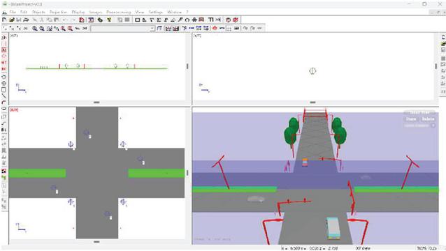
A general-purpose testbed environment for antenna testing, shown in Figure 1, is designed using Altair WallMan. The 3D cars, pedestrians, and traffic lights are placed in a V2X scenario to enable animated car and pedestrian movement over a three second time interval. The 3D models are sourced from libraries and training material included with the software license.
CAD models of pedestrians and cars are placed in a symmetrical configuration relative to the center of the intersection at zero. Exact coordinates are shown in Table 2. Note that the z-axis is raised 0.1 metres above the road to prevent overlapping topology.
The following far-field pattern is calculated for a finely meshed dipole antenna transmitting 5G-generation frequency bands designated by IEEE 802.11p for V2X to maximize render accuracy at 5.8 GHz, 6 GHz, and 28 GHz [18]. Computing the far-field radiation pattern produces a full wave, Method of Moments (MoM), and solution of Maxwell’s integral equations in the frequency domain for the desired antenna [19]. Using a finely meshed matrix in the MoM implies a limit to the size of the problem that can be solved. Available computational resources and time determine this limit.
Simulations are computed with software-verified far-field radiation patterns placed on cars and pedestrians to calculate optimal transmission capacity at millisecond time intervals. The computation time required to calculate results for each animation increases as more dipole antennas are introduced. A short animation time and symmetrical design are utilized to reduce computational complexity, verify repeatability of the study, and increase precision.
Figure 1 This figure shows a four-way intersection with four cars, four pedestrians, and four traffic lights designed in Altair WallMan. WallMan is CAD design software used to create indoor and outdoor databases that are compatible with ProMan (WinProp).
Table 2
| Various car and human CAD models are placed in Wallman at the x, y, and z coordinates shown here | |||
| X-axis | Y-axis | Z-axis | |
| (meters) | (meters) | (meters) | Name |
| 16.5 | 5.5 | 0.1 | Car0 (Round) |
| 16.5 | 5.5 | 0.1 | Car1 (Mercedes) |
| 4.0 | 15.5 | 0.1 | Car2 (Car) |
| 4.0 | 15.5 | 0.1 | Car3 (Minibus) |
| 10.0 | 11.0 | 0.1 | Person4 (F) |
| 10.0 | 11.0 | 0.1 | Person5 (M) |
| 10.0 | 11.0 | 0.1 | Person6 (F) |
| 10.0 | 11.0 | 0.1 | Person7 (M) |
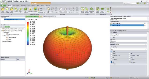
Figure 2 Far-field propagation pattern for a dipole antenna capable of transmitting a maximum power of 1.750 dBm at 6 GHz. The dipole model is included as a template in Altair FEKO and finely meshed to maximize far-field computation accuracy.
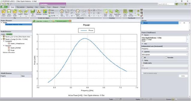
Figure 3 The active power of the dipole antenna in Figure 2 is shown here to peak between seven and eight milliwatts (mW) within the 5.8 GHz and 6 GHz frequency bands.
Table 3
| List of ProMan (WinProp) computations cycles performed and the time required to complete with a 12th Gen Intel(R) Core () i9-12900 CPU operating on four threads within a Windows 11 Professional operating system. Each computation is identified by frequency, antenna type, number of antennas, and SBR method | ||||
| Antenna | # of | Method | Time | |
| Frequency | Type | Antennas | (SBR) | (hour) |
| 5.8 GHz | Dipole | 2 | Prediction Rectangle | 8 |
| 5.8 GHz | Dipole | 2 | Predication Point | 2 |
| 6 GHz | Dipole | 2 | Prediction Rectangle | 8 |
| 28 GHz | Omni | 8 | Predication Point | 12 |
| 28 GHz | Omni | 8 | Prediction Rectangle | 72+ |
Based on the observed computation times, a prediction rectangle is ultimately used for the dipole antennas transmitting at 5.8 GHz and 6 GHz. A set of four metre-by metre square prediction points are placed above every crosswalk for the 28 GHz omnidirectional antenna calculations. These computations were done without any explicit form of graphics processing unit (GPU) acceleration or algorithms to generalize the SBR calculations [20].
This simulation is performed in the 5.8 GHz to 6 GHz range using the finely meshed far-field radiation pattern from a dipole antenna to yield results that verify the received power, in decibel-milliwatts (dBm), of current 5G-generation dipole antennas. The vehicles are animated to move at approximately 48.28 kilometres, or 30 miles, per hour and the pedestrians wait for the traffic to pass and cross the road at 4.82 kilometres, or 3 miles, per hour.
A transmitting antenna is placed just above the center of the Car0 roof at 1.6 metres. The received power is measured in a prediction rectangle placed directly in front of the vehicle at 1.5 metres above the crosswalk. This animation progresses from top to bottom in the left column and then the right column. The vehicle antenna remains attached to the animated car throughout the sequence.
The number of paths indicates the transmitted signal’s reflections, and the subsequent calculations performed during computation. To reduce the overall number of computations, Shooting Bouncing Ray (SBR) solver reflections were limited to two bounces per angle of transmission.
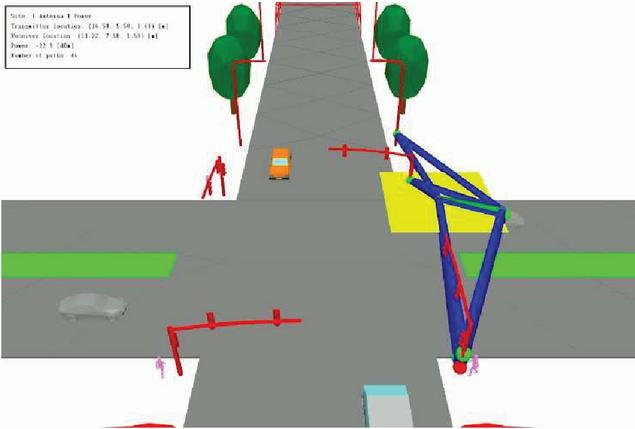
Figure 4 Power received above the crosswalk from the Car0 dipole antenna is shown in the prediction rectangle.
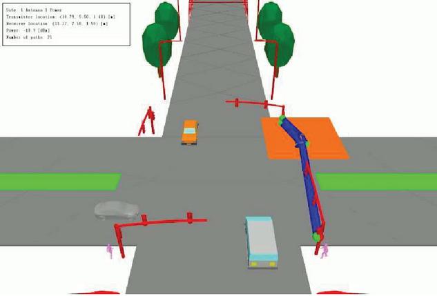
Figure 5 Power received is maximum and interference is minimal when the crosswalk is within line-of-sight.
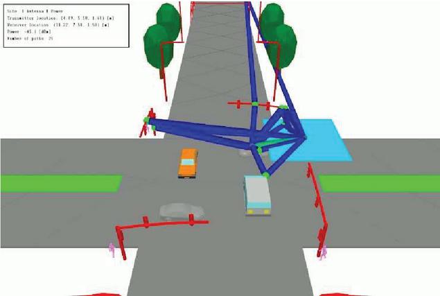
Figure 6 Though number of paths are increasing, received power is sufficient.
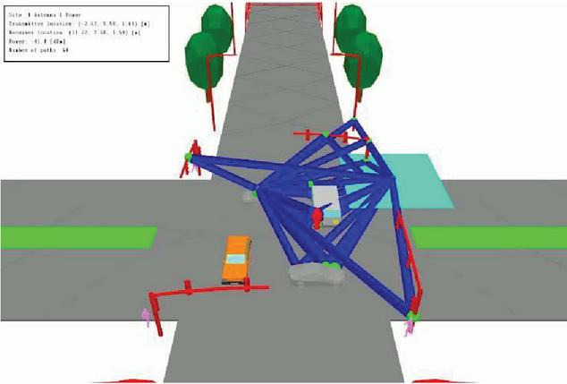
Figure 7 The number of paths increase significantly with vehicle obstruction.
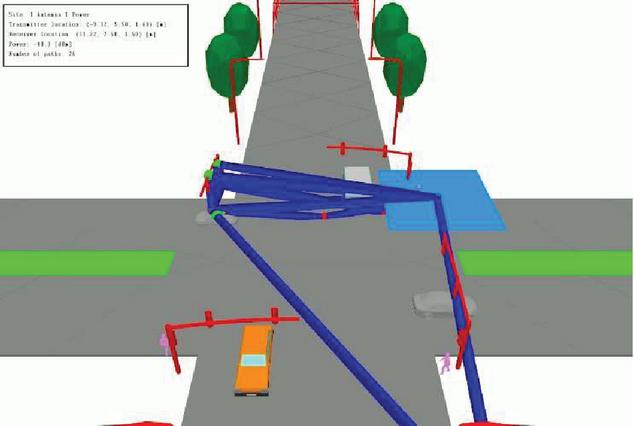
Figure 8 Received power decreases dramatically once Car0 completes pass.
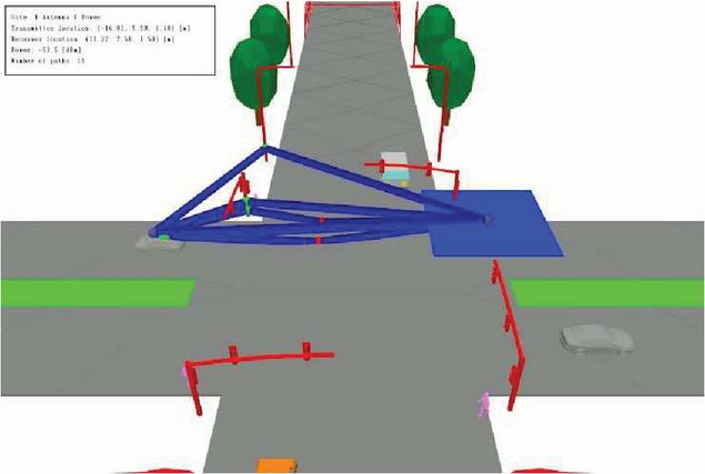
Figure 9 Power received is the weakest here, far behind the vehicle.
The sequence from Figure 4 through Figure 9 illustrates how the received power decreases as the number of reflections increases and the car drives further away. The symmetrical movement of all the cars within this animation is a significant contributor to this clustering of propagation paths, which means that typical traffic patterns in an intersection will present less interference overall. Though antenna arrays and beam-steering techniques may be introduced to mitigate and reduce noise from these reflections, it is essential to verify that a sufficient level of performance is possible with simple dipole antennas before introducing further complexity to the far-field radiation patterns.
Omnidirectional far-field radiation patterns included with and optimized in ProMan are used in the following 28 GHz simulation to reduce computational complexity further. This omnidirectional pattern is optimized for improved efficiency within the software. It reduces the chance of placement errors from importing finely meshed far-field radiation patterns from Altair FEKO. For this simulation, particular attention is placed on the received power at four square-metre prediction points placed at 1.5 metres above the intersection crosswalks.
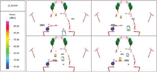
Figure 10 Omnidirectional antenna placed at waist level in front of Person6 and transmitting at 28 GHz.
The power received at the propagation points in Figure 10 from the pedestrian antenna remains consistent while the pedestrian waits for the traffic to pass. Any power received that reaches or exceeds 100 dBm is deemed sufficient for low latency transmission of packets containing critical proximity information.
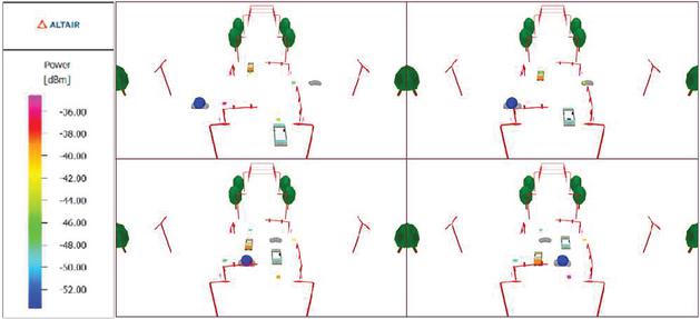
Figure 11 Omnidirectional antenna placed above the roof of Car1 and transmitting at 28 GHz.
Notice how in Figure 11 the received power decreases where other vehicles obstruct the propagation path, though the crosswalk points within the line-of-sight of the vehicle remain optimal. It is also important to note that once the car has passed the prediction point, there is no longer a need to transmit to the path or proximity of the pedestrian.
Vehicle-to-Everything (V2X) is a crash avoidance technology that relies on communicating information between nearby vehicles and infrastructure to warn drivers about potentially dangerous situations that could lead to crashes. Strong carrier signal power is received above a crosswalk from car and pedestrian antennas within a 10-metre radius of a potential reception point in the critical path of a moving car. Transmission is not significantly affected by dipole antenna placement in terms of azimuth and phase. It, therefore, presents evidence to support the potential for pedestrian safety-aware antenna configurations in low and high traffic intersections to assist in crash avoidance. By iteratively simulating this performance in a time-variant scenario over a critical three second period, it appears possible to test and develop ideal antenna configurations along with existing and emerging V2X systems and 5G-generation smartphone devices. These iterative simulation techniques reduce the overall costs of hardware testing and deployment, empowering radio frequency engineers to think creatively about network design decisions.
The School of Engineering and Engineering Technology at the University of Arkansas at Little Rock graciously provides facilities and funding for this project. Altair provides software documentation and technical support. Special thanks go to Dr. Seshadri Mohan and Vinod Kumar for their editorial support.
[1] ITF (2012), “Pedestrian Safety, Urban Space and Health,” In International Transport Forum, OECD Publishing, pages 116, Paris.
[2] Abdullah MFA, Yogarayan S, Abdul Razak SF et al (2023), “Edge computing for Vehicle to Everything: a short review” [version 4; peer review: 1 approved, 2 approved with reservations, 3 not approved]. F1000Research 2023, 10:1104.
[3] Arshi, O., Mondal, S. (2023), “Advancements in sensors and actuators technologies for smart cities: a comprehensive review,” Smart Constr. Sustain. Cities 1, 18.
[4] Patella, Sergio Maria, Simone Sportiello, Stefano Carrese, Francesco Bella, and Francesco Asdrubali (2020), “The Effect of a LED Lighting Crosswalk on Pedestrian Safety: Some Experimental Results” Safety 6, no. 2: 20.
[5] K. D. S. A. Munasinghe, T. D. Waththegedara, I. R. Wickramasinghe, H. M. O. K. Herath and V. Logeeshan (2022), “Smart Traffic Light Control System Based on Traffic Density and Emergency Vehicle Detection,” 2022 Moratuwa Engineering Research Conference (MERCon), Moratuwa, Sri Lanka, 2022, pp. 1–6.
[6] P. Kumar and K. B. Ali (2022), “Intelligent Traffic System using Vehicle to Vehicle (V2V) & Vehicle to Infrastructure (V2I) communication based on Wireless Access in Vehicular Environments (WAVE) Std,” 2022 10th International Conference on Reliability, Infocom Technologies and Optimization (Trends and Future Directions) (ICRITO), Noida, India, pp. 1–5.
[7] R. Weber, J. Misener and V. Park (2019), “C-V2X – A Communication Technology for Cooperative, Connected and Automated Mobility,” Mobile Communication – Technologies and Applications; 24, ITG-Symposium, Osnabrueck, Germany, pp. 1–6.
[8] F. A. Butt, J. N. Chattha, J. Ahmad, M. U. Zia, M. Rizwan and I. H. Naqvi (2022), “On the Integration of Enabling Wireless Technologies and Sensor Fusion for Next-Generation Connected and Autonomous Vehicles,” in IEEE Access, vol. 10, pp. 14643–14668.
[9] Syed Adnan Yusuf, Arshad Khan, Riad Souissi (2024), “Vehicle-to-everything (V2X) in the autonomous vehicles domain – A technical review of communication, sensor, and AI technologies for road user safety,” Transportation Research Interdisciplinary Perspectives, Volume 23.
[10] J. van Tonder et al. (2023), “Latest Features in Altair Feko 2022,” 2023 International Applied Computational Electromagnetics Society Symposium (ACES), Monterey/Seaside, CA, USA, pp. 1–2.
[11] H. Hultin, H. Frid, B. L. G. Jonsson and J. Malmström (2024), “Investigation of Near-Field Contribution in Shooting and Bouncing Rays for Installed Antenna Performance on a Simple Platform,” 2024 18th European Conference on Antennas and Propagation (EuCAP), Glasgow, United Kingdom, pp. 1–5.
[12] E. H. Newman (1988), “Simple examples of the method of moments in electromagnetics,” in IEEE Transactions on Education, vol. 31, no. 3, pp. 193–200.
[13] Christian Ballesteros, Luca Montero, Germán A. Ramírez, Luis Jofre-Roca (2022), “Multi-antenna 3D pattern design for millimeter-wave vehicular communications,” Vehicular Communications, Volume 35.
[14] Raiful Hasan, Ragib Hasan (2022), “Pedestrian safety using the Internet of Things and sensors: Issues, challenges, and open problems,” Future Generation Computer Systems, vol. 134, pp. 187–203.
[15] L. Italiano, B. C. Tedeschini, M. Brambilla and M. Nicoli (2024), “Pedestrian Positioning in Urban Environments with 5G Technology,” 2024 22nd Mediterranean Communication and Computer Networking Conference (MedComNet), Nice, France, pp. 1–6.
[16] R. Dilli (2020), “Analysis of 5G Wireless Systems in FR1 and FR2 Frequency Bands,” 2020 2nd International Conference on Innovative Mechanisms for Industry Applications (ICIMIA), Bangalore, India, pp. 767–772.
[17] A. Xia et al. (2018), “28 GHz MIMO Channel Capacity Analysis for 5G Wireless Communication Systems,” 2018 12th International Symposium on Antennas, Propagation and EM Theory (ISAPE), Hangzhou, China, pp. 1–4.
[18] T. Zugno, M. Drago, M. Giordani, M. Polese and M. Zorzi (2020), “NR V2X Communications at Millimeter Waves: An End-to-End Performance Evaluation,” GLOBECOM 2020 – 2020 IEEE Global Communications Conference, Taipei, Taiwan, pp. 1–6.
[19] Maxwell, James Clerk (1865). “A Dynamical Theory of the Electromagnetic Field.” Philosophical Transactions of the Royal Society of London, vol. 155.
[20] D. Shi, X. Tang and C. Wang (2017), “The acceleration of the shooting and bouncing ray tracing method on GPUs,” 2017 XXXIInd General Assembly and Scientific Symposium of the International Union of Radio Science (URSI GASS), Montreal, QC, Canada, pp. 1–3.

Colin McNerny is pursuing his Bachelor of Science in Electrical and Computer Engineering at the University of Arkansas at Little Rock. He works as a research assistant at the Emerging Analytics Center and retains a Bachelor of Arts in English and Creative Writing from the University of Arkansas at Fayetteville.

Haley Burt is a recent alumna from the University of Arkansas at Little Rock with her B.S. in Electrical and Computer Engineering. Haley currently works at Jacobs Technology at Kennedy Space Center in Florida.

Hussain Al-Rizzo received his PhD in Electrical and Computer Engineering from the University of New Brunswick, Canada. In 2000, he joined the Systems Engineering Department at the University of Arkansas at Little Rock, where he is currently a Professor of Telecommunication Systems Engineering. He has published over 300 papers in peer-reviewed journals and conference proceedings, two books, eight book chapters, and four patents. His research areas include V2V, V2X, and V2I wireless systems; smart antennas; massive MIMO; flexible RF components and antennas; implantable medical devices; electromagnetic wave scattering by complex objects; design, modeling, and testing of high-power microwave applicators; precipitation effects on GPS; terrestrial and satellite frequency re-use communication systems; field operation of NAVSTAR GPS receivers; data processing and accuracy assessment; and effects of the ionosphere, troposphere, and multipath on code and carrier-beat phase GPS observations.

Abhigna Maturi, PhD Student in the Department of Electrical and Computer Engineering and working as a Graduate Teaching Assistant for two courses at University of Arkansas at Little Rock, United States, since August 2022. Completed Master of Technology in Communication and Radar Systems Engineering from Koneru Lakshmaiah Education Foundation, India in May 2020 and received a Silver Medal for academic performance. She published a Journal paper in Acta Geophysica as a main author in her Master’s degree as a part of Indian Space Research Organization (ISRO) sponsored project. Her current and previous research areas include Beamforming of Antennas, Massive MIMO, V2X, V2I, V2V, effects of ionosphere on GPS, GNSS.