High-Frequency Dual-Band Super-Compact MIMO Antenna for Resilient 5G Vehicular Communications
Moustafa M. Nasralla, Mehr E Munir* and Haleem Farman
Smart Systems Engineering Laboratory, Department of Communications and Networks Engineering, College of Engineering, Prince Sultan University, PO BOX 66833, Riyadh, 11586, Saudi Arabia
E-mail: mnasralla@psu.edu.sa; mmunir@psu.edu.sa; hfarman@psu.edu.sa
*Corresponding Author
Manuscript received 20 November 2025, accepted 14 June 2026, and ready for publication 22 July 2026.
© 2026 River Publishers
DOI. No. 10.13052/2794-7254.035
Abstract
In 5G vehicular services, advanced antenna systems are essential to deliver robust, reliable, and efficient wireless links under real driving conditions. Vehicles operate in highly dynamic and interference-prone radio environments, where signals are frequently obstructed by surrounding objects and rapidly changing mobility patterns. Moreover, the limited physical space available for on-board electronics further constrains antenna design. These factors collectively hinder the deployment of reliable high-capacity links, highlighting the need for advanced, compact, and resilient antenna systems tailored for vehicular communications. To meet these constraints, this paper presents a high-frequency, dual-band, super-compact MIMO antenna designed for resilient 5G vehicular communications. The proposed antenna is designed on 0.51 mm RO4350B substrate and operates in two widely separated bands 8–11 GHz (microwave band) and 24–34 GHz (mmWave band) so that a single element can support both dependable coverage and high-capacity services. The design incorporates five vertical slots integrated with three horizontal slots on patch while a partial ground plane with a square slot is incorporated on ground plane. In the 8–11 GHz range, the antenna achieves a peak gain of 4.64–5.99 dBi while in the 24–34 GHz, it provides a peak gain of 4.7–6.4 dBi, enabling high data rates and low latency for demanding applications. Across both ranges, the antenna maintains 90% radiation efficiency, while isolation between radiating elements exceeds 19 dB, ensuring reliable and energy-efficient operation. The design features a mm3 footprint on an RO4350B substrate, making it well-suited to space-constrained vehicular platforms. Furthermore, experimental validation and link-budget analysis on a vehicular model confirm the antenna’s promising performance. By combining dual-band functionality, high efficiency, compact dimensions, and validated performance, the proposed antenna addresses user needs, service requirements, and high-frequency technology demands essential for next-generation, resilient 5G vehicular communication systems. Its dual-band capability enhances spectrum flexibility and supports diverse vehicular communication scenarios, including advanced driver-assistance systems (ADAS), vehicle-to-everything (V2X) connectivity, and high-data-rate services.
Keywords: Dual band, MIMO Antenna, mmWave antenna, X-band, 5G.
1. Introduction and Related Work
Modern in-vehicle radios are being designed to work across X-band (8–12 GHz) and mmWave (24–300 GHz) so a single platform can deliver two complementary functions: dependable mid-band coverage for control and V2X safety, and very high-capacity, low-latency links for ADAS telemetry, cooperative perception, and infotainment. This dual role forces the antenna to meet three tough requirements at once: it must be ultra-compact to fit inside tight housings (e.g., shark-fin or mirror pods), highly efficient despite the small electrical size and nearby lossy materials, and well matched with stable radiation patterns across two widely separated bands. Consequently, even with recent advances in compact dual-band and miniaturized mmWave arrays (e.g., around 28/38 GHz), achieving high efficiency in a very small form factor while simultaneously supporting a separated lower band remains a primary integration challenge [1].
The authors in [2] designed a mmWave antenna for wearable devices operating at 28 and 38 GHz, with overall dimensions of mm3. It supports only two bands and provides a narrow impedance bandwidth of 1 GHz at each frequency. Moreover, the footprint is relatively large, making it unsuitable for many practical 5G wearable applications. The authors in [3] presented an antenna for vehicular applications operating in three bands 1.565–1.578 GHz, 2.2–3.8 GHz, and 5.8–6 GHz with overall dimension of mm3. Despite covering multiple bands, the design exhibits a very narrow impedance bandwidth, and its large footprint makes it unsuitable for practical 5G vehicular deployments. The authors in [4] designed a 5G mmWave antenna for vehicular applications targeting the n258 band (24.25–27.5 GHz) on a Rogers RO4003C substrate. The design achieved peak gains of 4.6 and 5.15 dBi, but it operates in only a single band. For modern vehicular 5G platforms, dual-band or multi-band operation is typically required to ensure efficient, versatile performance. The authors in [5] designed a mmWave MIMO antenna operating at the 28 and 38 GHz bands, using a defected patch structure with overall dimensions of mm2. The antenna exhibits good impedance bandwidth and solid MIMO performance; however, its large footprint makes it unsuitable for many practical 5G devices.
The authors in [7] present a two-element dual-band MIMO antenna using an inset-fed primary patch and an overlaid arc-shaped parasitic to realize operation at 28 GHz and 38 GHz with strong isolation (20 dB) while maintaining a compact footprint illustrating a clean pathway to dual-band miniaturization via parasitic loading and ground tailoring. A noted trade-off is the modest realized gain (1–2 dB in cited comparisons), which may be insufficient for harsher outdoor/vehicular links without arraying or additional aperture engineering. A dual-band array targeting 28/38 GHz with higher realized gain and wider impedance bandwidth is reported in [8], and is useful for terminals requiring both diversity and directional performance. The studies document multi-port arrangements with isolation control and report high-gain variants suitable for mmWave links. A limitation is that increasing port count and gain often demands tighter layout tolerances and can introduce pattern distortion in constrained housings practical concerns for vehicular body-integrated installations. In [9], the authors propose an arc-shaped, very small 28 GHz radiator (monopole radius 1.3 mm) with an elliptical slot to enhance bandwidth ssssan appealing seed element for dense MIMO tiling where board area is scarce. The main drawback is that extreme miniaturization can constrain efficiency and gain, so multiple elements or superstrates may be required to meet link budgets in dynamic vehicular channels. In [10], surveys how GNSS/IMU/side-information can prune mmWave beam search, reduce training overhead, and stabilize links directly relevant to “resilience” when antennas are mounted on fast-moving vehicles and frequent blockages occur. The limitation is that this is a protocol/algorithmic perspective rather than a hardware design; it improves link continuity but does not by itself solve RF constraints such as mutual coupling or element efficiency. In [11], the authors compile vehicular-centric measurements and models, highlighting blockage, Doppler, and fast fading in V2V/mmWave scenarios, and outlining the array requirements imposed by these channel dynamics. The main limitation for immediate design guidance is that, as a broad survey, it does not prescribe exact antenna geometries or isolation techniques; translating channel insights into PCB-level MIMO layouts remains the designer’s task. Similarly, in [12], the authors introduce a circular, double-sided EBG texture to suppress surface waves and improve isolation in a compact dual-band MIMO design (with single-element mm2 and MIMO mm2). This is a proven, fabrication-friendly approach to reducing ECC without requiring large spacing’s. The caveat is added stack-up complexity: EBG/DGS patterns increase design and fabrication effort and can complicate multi-board integration or conformal vehicle mounting.
The proposed design is a high-frequency, dual-band, super-compact MIMO antenna for resilient 5G vehicular communications. It covers 8–11 GHz and 24–34 GHz, achieving peak gains of 4.64–5.99 dBi (microwave band) and 4.64–5.99 dBi (mmWave band), while maintaining 90% radiation efficiency in both bands. The antenna was also tested on a vehicular model, where it demonstrated strong performance, confirming its suitability for practical 5G vehicular applications.
2. MIMO Antenna Design
The proposed MIMO antenna is lightweight, compact, simple to fabricate, and easy to integrate with X-band and mmWave devices. It is designed and optimized using CST Studio Suite 2022 and a low-loss microwave laminate such as RO4350B is employed to support high radiation efficiency in both bands while remaining PCB-process friendly. This material choice helps achieve 90% efficiency while keeping the stack-up simple for automotive modules. The present work reports results only in the mmWave band [6], while an extended version of the same design enables operation over 8–11 GHz (microwave band) and 24–34 GHz (mmWave band), with a total size of mm3, and has been experimentally tested on a vehicle CAD model. The design leverages three techniques:
2.1 DPST Technique
A defected patch structure technique (DPST) means that the normal metal patch of the antenna is intentionally modified by introducing slots or cuts. These slots alter the surface current paths, allowing the patch to support more than one natural resonant frequency instead of a single band. As a result, the same compact patch can generate multiple resonances, enabling multiband or wider-band operation without increasing the overall antenna size (see Figure 1).
2.2 Partial Ground Plane Technique
A partial ground plane means the ground metal is intentionally shortened rather than covering the full substrate, which helps improve impedance matching and bandwidth. In this design, a square slot is etched in the ground to further tune the resonance and extend the usable frequency range, as shown in Figure 2.
2.3 Connected Ground Plane Technique
The connected ground plane approach means that all four antenna elements are tied to the same continuous ground instead of having separate grounds. Arranged in a linear array, these four elements sharing a common ground help achieve compact integration and better MIMO performance, as illustrated in Figure 2.
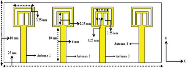
Figure 1 Front view of MIMO antenna [6].

Figure 2 Back view of MIMO antenna [6].
3. Results and Discussions
The proposed MIMO antenna operates over two bands, 8–11 GHz in the microwave range and 24–34 GHz in the mmWave range, as illustrated in Figure 3, making it well suited for practical 5G vehicular applications. In the lower band, the antenna achieves a 3 GHz impedance bandwidth, providing robust coverage across the entire X-band allocation of interest. In the upper band, it offers a much wider 10 GHz bandwidth, which is beneficial for high-data-rate mmWave links and multi-service integration. Together, these dual bands enable flexible support for long-range sensing/communications and high-capacity 5G links on vehicles. In this design, the port isolation is 19 dB in both the lower and upper operating bands (see Figure 4), meaning that only a small amount of power from one element couples into the others across the full spectrum. Maintaining this low coupling over 8–11 GHz and 24–34 GHz helps preserve the independence of the MIMO channels and reduces inter-port interference. As a result, the antenna can deliver more reliable diversity and capacity performance for wideband vehicular 5G links.
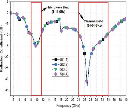
Figure 3 S-parameter of MIMO antenna.
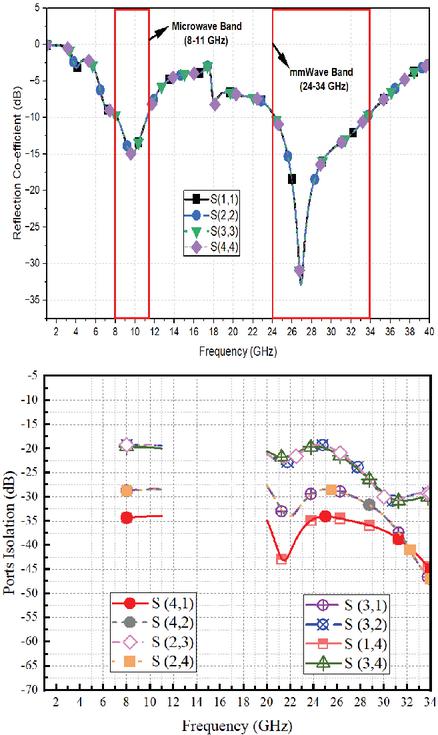
Figure 4 Port isolation of MIMO.
The proposed MIMO antenna demonstrates strong performance in terms of gain, radiated efficiency, and total efficiency, as shown in Figure 3. At 11 GHz, it achieves a gain of 5.89 dBi with a radiated efficiency of 92% and a total efficiency of 88%. At 28 GHz, the gain increases to 6.4 dBi, with a radiated efficiency of 95.85% and a total efficiency of 92.5%, confirming its suitability for NR 5G bands. Figure 4 presents the fabricated four-element MIMO antenna prototype, validating the practicality of the design.
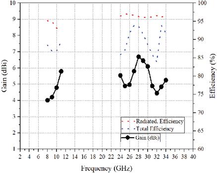
Figure 5 Gain, radiated and total efficiency.
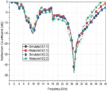
Figure 6 Simulated and measured reflection co-efficient.
Figure 6 compares the simulated and measured reflection coefficient of the proposed four-element MIMO antenna. The measured curves closely follow the simulated ones, with only minor deviations mainly attributed to connector and fabrication losses. This close agreement confirms that the antenna maintains its intended impedance matching and bandwidth in practice. The strong correlation between simulation and measurements verifies the design’s suitability for sustainable 5G vehicular networks. The antenna under test is presented in Figure 7, where its physical layout and feeding configuration can be clearly observed. The corresponding 3D gain pattern at 11 GHz is illustrated in Figure 8, highlighting the main radiation lobes and overall directivity.
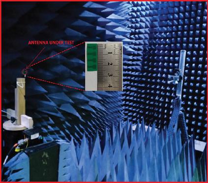
Figure 7 MIMO antenna under test.
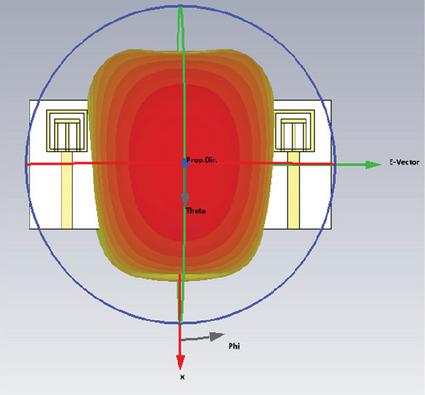
Figure 8 3D gain at 11 GHz.
4. MIMO Performance Evaluation
The proposed four-element MIMO array is further assessed through key performance metrics to verify its effectiveness and overall performance capability.
The diversity gain (DG) presents the performance of four antenna ports, labeled DG1 to DG4, across the frequency range of 2 to 40 GHz, as shown in Figure 9.
DG quantifies the effectiveness of a MIMO antenna in mitigating multipath fading. A value near 10 dB is generally regarded as optimal for MIMO diversity performance [19]. In the presented results, all four DG curves remain close to 10 dB within both operating bands:
• 8 to 11 GHz: DG is approximately 9.99 dB to 10 dB
• 24 to 34 GHz: DG is approximately 9.99 dB to 10 dB
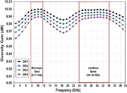
Figure 9 DG of the proposed 4-port MIMO.
These results indicate that the four ports are sufficiently de-correlated and are capable of providing strong diversity performance. Minor variations among DG1, DG2, DG3, and DG4 are expected, as each antenna port may exhibit slightly different coupling and radiation characteristics. The results demonstrates that the antenna achieves excellent diversity performance in both the microwave and mmWave bands. A DG value exceeding approximately 9.95 dB is commonly used as a benchmark for strong MIMO diversity behavior.
Figure 10 shows the envelope correlation coefficient (ECC) of the proposed 4-port MIMO antenna across 2–40 GHz, with the two intended operating bands highlighted in red: 8–11 GHz and 24–34 GHz.
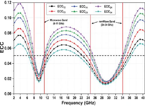
Figure 10 ECC of the proposed 4-port MIMO antenna.
ECC is an important MIMO performance parameter because it measures the correlation between antenna elements. Lower ECC means the antenna ports are more independent, which improves diversity performance and helps the MIMO system transmit/receive multiple data streams more efficiently. ECC is directly related to diversity behavior; when ECC is low, the diversity gain approaches the ideal value of 10 dB [18].
In Figure 10, the ECC curves are plotted for different port combinations, such as ECC12, ECC13, ECC14, ECC23, ECC24, and ECC34. These curves represent the correlation between each pair of antenna ports in the 4-port structure. Within the first operating band, 8–11 GHz, all ECC values drop significantly and remain low, mostly around 0.015–0.05. This means the antenna elements have weak correlation in the microwave band, confirming good isolation and diversity behavior. Within the second operating band, 24–34 GHz, the ECC values are also low, especially near the center of the band, 27–30 GHz, where several curves approach 0.01–0.02. Toward the upper edge near 33–34 GHz, the ECC increases slightly but remains in the acceptable low-correlation region.
Figure 11 presents the Channel Capacity Loss (CCL) as the expected reduction in MIMO channel capacity resulting from correlation and mutual coupling between antenna elements.
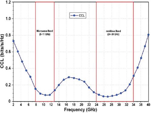
Figure 11 CCL of the proposed 4-port MIMO antenna.
For practical MIMO antennas, the stocktickerCCL should typically remain below 0.4 bits/s/Hz [17]. In the presented results, the stocktickerCCL remains well below this threshold across both operating bands:
• 8–11 GHz: The CCL is approximately 0.05 to 0.15 bits/s/Hz.
• 24–34 GHz: The CCL is approximately 0.05 to 0.15 bits/s/Hz.
These results indicate that the proposed four-port antenna exhibits low inter-port correlation and minimal capacity degradation. Consequently, the antenna can support efficient MIMO data transmission without significant loss in channel capacity. This characteristic is critical for practical 5G and millimeter-wave (mmWave) systems, as elevated CCL values would reduce spectral efficiency and data throughput. Several MIMO antenna studies consider CCL values below 0.4 bits/s/Hz as an acceptable practical limit.
The total active reflection coefficient (TARC) behavior of the 4-port MIMO antenna when all ports are excited simultaneously. This is more realistic than evaluating only the individual S11, S22, S33, or S44 values because, in a MIMO system, multiple ports operate simultaneously. Figure 12 shows three cases:
• TARC, in-phase: all ports excited with the same phase.
• TARC, average phase: average response for different excitation phases.
• TARC, worst phase: worst-case reflection under phase variation.
The dashed horizontal line at 10 dB is the practical matching reference. In both highlighted operating bands, the TARC curves remain below 10 dB, which means the antenna maintains acceptable active impedance matching when all four ports are excited [16].
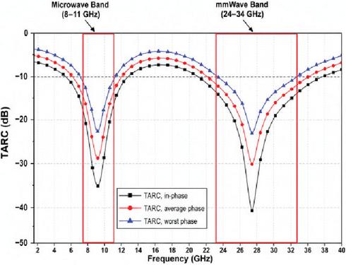
Figure 12 TARC of the proposed 4-port MIMO antenna.
The graph shows strong TARC dips at approximately 9 GHz and 28 GHz, where TARC values are very low. These deep minima indicate strong resonance and low reflected power. In the 8–11 GHz band, the curves fall well below 10 dB, confirming good active matching. In the 24–34 GHz band, the TARC also stays below 10 dB over the operating region, confirming stable mmWave MIMO operation.
5. Car Model Analysis
To assess the real-world performance of the proposed antenna, it is placed on an EV Tesla car CAD model, representing a practical vehicular installation scenario, as shown in Figure 13. The electromagnetic simulation is then carried out on this full vehicle model using a high meshing density of 17 cells per wavelength to accurately capture all coupling and scattering effects. This fine mesh ensures that subtle interactions between the antenna and the car body are properly resolved. Remarkably, the simulated S-parameters remain essentially unchanged compared to the standalone case, as shown in Figure 14, while the antenna continues to operate effectively in both the X-band (8–11 GHz) and the mmWave band (24–34 GHz). This confirms that the antenna preserves its matching and isolation characteristics on the vehicle, demonstrating reliable and consistent performance in a realistic automotive environment.
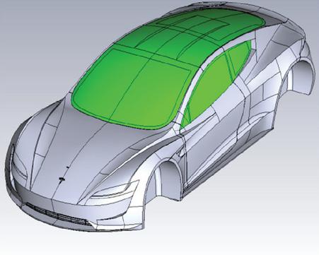
Figure 13 EV Tesla car CAD model.
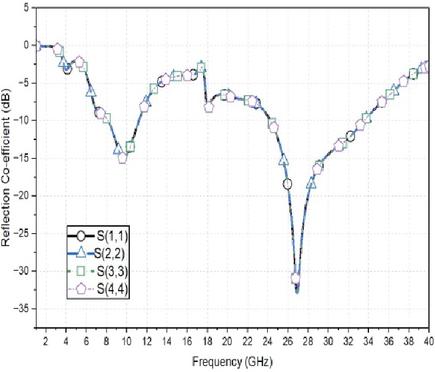
Figure 14 EV Tesla car CAD model.
The gain in the lower band (8–11 GHz) ranges from 8.02 dBi to 9.06 dBi, while in the upper band (24–34 GHz) it varies from 7.23 dBi to 9.22 dBi, highlighting the effectiveness of the proposed design. Specifically, the 3D gain at 9 GHz reaches 9.06 dBi, demonstrating strong radiation performance in the X-band. Similarly, at 28 GHz, the 3D gain increases to 9.22 dBi, as illustrated in Figures 15(a) and 15(b), confirming robust operation in the mmWave band.
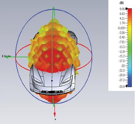
Figure 15(a): 3D gain at 9 GHz for the antenna integrated with the car CAD model.
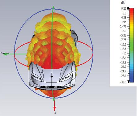
Figure 15(b): 3D gain at 28 GHz for the antenna integrated with the car CAD model.
The radiation patterns in both the lower band (8–11 GHz) and the upper band (24–34 GHz) are directive, meaning the radiated energy is concentrated into a main lobe with higher gain and reduced side and back lobes, which is beneficial for focused links and improved link budgets. At 11 GHz, the main lobe magnitude is 8.91 dBi, the main lobe direction is 0∘, the 3 dB angular-width is 58.4∘, and the side lobe level is 2.4 dB, as shown in Figure 16(a). At 28 GHz, the main lobe magnitude increases to 9.19 dBi, the main lobe direction shifts slightly to 5∘, the 3 dB angular width narrows to 43∘, and the side lobe level is 2.9 dB, as also illustrated in Figure 16(a). These results confirm that the antenna maintains a stable, directive beam over both operating bands.
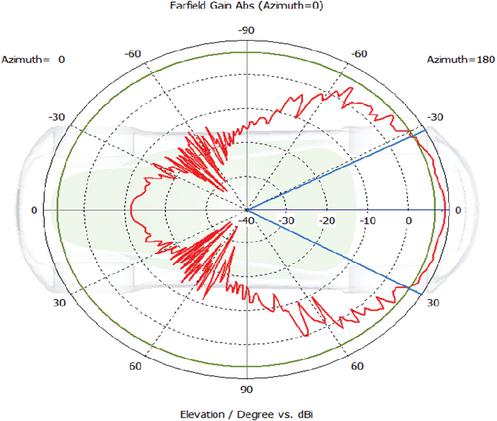
Figure 16(a): Radiation Pattern at 9 GHz for the antenna integrated with the car CAD model.
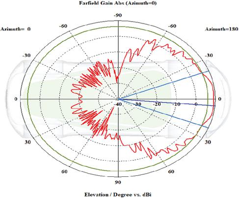
Figure 16(b): Radiation Pattern at 12 GHz for the antenna integrated with the car CAD model.
The E-field distribution is also evaluated at 28 GHz, where the maximum E-field is observed to be 200 V/m. The results show that the antenna’s radiation is largely confined to the region where the antenna is mounted on the car. The fields do not significantly propagate into other parts of the vehicle body, indicating minimal unwanted coupling or scattering. This localization of radiation confirms that the antenna operates efficiently on the designated mounting area without adversely affecting the rest of the car structure, as shown in Figure 17.
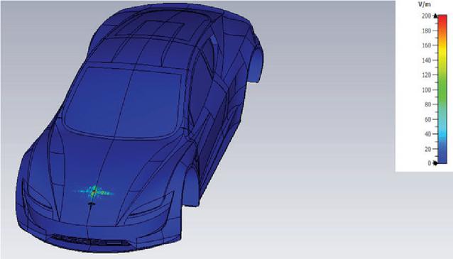
Figure 17 E-Field analysis 28 GHz.
6. Car Link Budget Analysis
The mathematical analysis of the car link budget is based on the Friis transmission equation expressed in dB, where the received power is calculated by adding the transmit power and antenna gains and subtracting the free-space path loss and other system losses. The free-space path loss is computed using [13, 14, 15], which demonstrates how both distance and frequency significantly affect signal attenuation. The received power is then compared with the total noise power, derived from the thermal noise floor, system bandwidth, and receiver noise figure, to calculate the signal-to-noise ratio (SNR). The link budget calculation is presented in Table 1.
Table 1
| Link budget analysis of the proposed MIMO antenna for car communication | |||
| Parameter | Equation/Value | Case A: 9 GHz, 100 m | Case B: 28 GHz, 100 m |
| Frequency | 9000 MHz | 28000 MHz | |
| Distance | 0.1 km | 0.1 km | |
| Transmit power | 20 dBm | 20 dBm | |
| Tx antenna gain | 9.06 dBi | 9.22 dBi | |
| Rx antenna gain | 9.06 dBi | 9.22 dBi | |
| System losses | 3 dB | 3 dB | |
| FSPL | 91.52 dB | 101.38 dB | |
| Received power | 56.40 dBm | 65.94 dBm | |
| Bandwidth | B | 100 MHz | 100 MHz |
| Thermal noise | 94 dBm | 94 dBm | |
| Noise figure | NF | 5 dB | 5 dB |
| Total noise power | 89 dBm | 89 dBm | |
| SNR | 32.60 dB | 23.06 dB | |
The calculated SNR for the proposed car link shows strong performance in both operating bands. In the lower band around 9 GHz, using a transmit power of 20 dBm, antenna gains of about 9.06 dBi at both ends, a 100 m link distance, and 3 dB system loss, the received power is approximately 56.4 dBm. With a 100 MHz bandwidth and a receiver noise figure of 5 dB, this corresponds to an SNR of about 32.6 dB, which is suitable for high-order modulation and robust 5G links. In the upper band around 28 GHz, the higher path loss reduces the received power to roughly 65.54 dBm, giving an SNR of about 23.46 dB, which is still comfortably above the threshold for reliable NR 5G operation and high data rates in vehicular scenarios.
7. Conclusion
The proposed design is a high-frequency, dual-band, super-compact MIMO antenna developed for resilient 5G vehicular services. It covers 8–11 GHz (microwave band) and 24–34 GHz (mmWave band), delivering peak gains of 4.64–5.99 dBi in the lower band and 4.7–6.4 dBi in the upper band, while maintaining radiation efficiency greater than 90% across both bands. The inter-element isolation is -19 dB supports stable MIMO operation and facilitates RF coexistence on space-constrained automotive platforms. The antenna is fabricated on an RO4350B substrate with a compact size of mm3, and when mounted on a vehicular CAD model it preserves its reflection characteristics and achieves a realized gain of 9.06 dBi at 9 GHz and 9.22 dBi at 28 GHz, indicating robust performance under realistic installation conditions. The link-budget analysis confirms strong performance in both the 8–11 GHz and 24–34 GHz bands, with SNR values of approximately 32.6 dB at 9 GHz and 23.46 dB at 28 GHz, providing ample margin for high-order modulation, reliable connectivity, and high data rates. Furthermore, the antenna addresses key requirements for next-generation vehicular links resilience, spectrum flexibility, energy-aware operation, and ease of integration and is well suited for V2X safety messaging, ADAS telemetry, and high-data-rate services that demand both dependable coverage and mmWave capacity.
Acknowledgment
The authors would like to acknowledge the support of Prince Sultan University in covering the conference expenses for this publication. This article is derived from are search grant funded by the Research, Development, and Innovation Authority (RDIA)-Kingdom of Saudi Arabia-with grant number (13292-psu-2023-PSNU-R-3-1-EF-.
References
[1] Munir, M. E., Nasralla, M. M., and Esmail, M. A. (2025, June). Design and Analysis of 8 1 Wideband Mmwave MIMO Antenna Array for High-Performance 5G UAV Communications. In 2025 IEEE 101st Vehicular Technology Conference (VTC2025-Spring) (pp. 1–7). IEEE.
[2] Tiwari, R. N., Sharma, D., Singh, P., and Kumar, P. (2024). A flexible dual-band MIMO antenna for 5G mm-wave 28/38 GHz wearable applications. Scientific reports, 14(1), 14324.
[3] Li, M., Su, Y., Zhang, W., and Lin, X. (2024). A versatile shared-aperture antenna for vehicle communications. Electronics, 13(20), 4009.
[4] Saleh, S., Saeidi, T., Timmons, N., Althuwayb, A. A., and Razzaz, F. (2025). Compact 5 G mmWave vivaldi antenna for vehicular communication. Vehicular Communications, 53, 100893.
[5] Awan, W. A., Abbas, A., Choi, D., Hussain, N., Lee, H., Sim, D., and Kim, N. (2025). Compact and Directional Dual Band Antenna with Low Mutual Coupling MIMO Configuration for mm-Wave Communication. Results in Engineering, 105457.
[6] Nasralla, M. M., Munir, M. E., Farman, H., and Choudhury, N. (2025). Design and Analysis of Millimeter-wave Antenna for New Radio (NR) 5G Bands Supporting a Green Wireless Future. Wireless World Research and Trends Magazine, 9–14.
[7] Esmail, B. A. F., et al. “Dual-band millimetre wave MIMO antenna with reduced mutual coupling,” Scientific Reports, 2024.
[8] Aghoutane, B., et al. “A novel dual band high gain 4-port millimeter wave MIMO antenna array for 28/38 GHz 5G applications,” AEU – International Journal of Electronics and Communications, 2022/2023.
[9] Kumar, P., et al. “An Ultra-Compact 28 GHz Arc-Shaped Millimeter-Wave Antenna,” Micromachines, 2022.
[10] Nor, A. M., et al. “Survey on positioning-information assisted mmWave beam training,” Computer Networks, 2022.
[11] Eldowek, B. M., et al. “A survey of 5G millimeter wave, massive multiple-input multiple-output, and vehicle-to-vehicle channel measurements and models,” International Journal of Communication Systems, 2021.
[12] Tu, D. T. T., et al. “Improving Characteristics of 28/38 GHz MIMO Antenna for 5G Applications by Using Double-Side EBG Structure,” Journal of Communications, 2019.
[13] Kashif, H., Shabbir, N., and Ojaide, U. S. C. Matlab Toolbox for Link Budget Analysis in Wireless Networks.
[14] Kim, H. (2015). Wireless communications systems design. John Wiley & Sons.
[15] Pedraza, L. F., Hernández, C. A., and López, D. A. (2017). A Model to Determine the Propagation Losses Based on the Integration of Hata-Okumura and Wavelet Neural Models. International Journal of Antennas and Propagation, 2017(1), 1034673.
[16] Munir, M. E., Nasralla, M. M., and Esmail, M. A. (2024). Four port tri-circular ring MIMO antenna with wide-band characteristics for future 5G and mmWave applications. Heliyon, 10 (8), e28714.
[17] Ali, A., Munir, M. E., Nasralla, M. M., Esmail, M. A., Al-Gburi, A. J. A., and Bhatti, F. A. (2024). Design process of a compact tri-band MIMO antenna with wideband characteristics for sub-6 GHz, Ku-band, and millimeter-wave applications. Ain Shams Engineering Journal, 15(3), 102579.
[18] Sehrai, D. A., Munir, M. E., Kiani, S. H., Shoaib, N., Algarni, A. D., Elmannai, H., … and Ali, T. (2024). A high gain array based millimeter wave MIMO antenna with improved isolation and decorrelated fields. IEEe Access, 12, 89794–89803.
[19] Sethi, W. T., Kiani, S. H., Munir, M. E., Sehrai, D. A., Savci, H. S., and Awan, D. (2024). Pattern diversity based four-element dual-band MIMO patch antenna for 5G mmWave communication networks. J. Infrared Milli Terahz Waves. 45, 521–537 (2024).
Biographies

Moustafa M. Nasralla (SM’21) received the B.Sc. degree(Hons.) in electrical engineering from Hashemite University, Jordan, in 2010, the M.Sc. degree in networking and data communications from Kingston University, London, U.K., in 2011, and the Ph.D. degree from the Faculty of Science, Engineering and Computing (SEC), Kingston University, London, U.K., in 2015. He is currently an Associate Professor and Chairman of the Department of Communications and Networks Engineering, Prince Sultan University (PSU), Riyadh, Saudi Arabia. He is currently the leader of the Smart Systems Engineering Laboratory (SSEL) at PSU. He was a member of the Wireless Multimedia and Networking (WMN) Research Group at Kingston University. He served as an active reviewer and received several distinguished reviewer awards from reputable journals, such as IEEE Transactions on Wireless Communications, IEEE Transactions on Multimedia, IEEE Transactions on Vehicular Technology, Wireless Communications (Elsevier), and Computer Network (Elsevier). He has solid research contributions in the area of networks and data communications, which are proven with publications in reputable journals with ISI Thomson JCR. He has won several national and internationally funded projects, such as Intelli-Student for the British Council, 5G-enabled Smart City Development for RDIA in Saudi Arabia, U.K. Home Office, and EU FP7 CONCERTO. Currently, he is serving as a Guest Editor for Alexandria Engineering Journal (Elsevier), International Journal of Distributed Sensor Networks (SAGE), Journal of Communications and Networks (Frontiers), and an Organizer of the International Conference on Sustainability: Development sand Innovations, and the 5G-Enabled Smart Cities workshop in the IEEE International Conference on Smart Cities. Moreover, he is a Senior Member of IEEE, a member of IEEE ComSoc, and the Association of Computing Machinery (ACM). He has published over 100 articles in high-impact factor journals and reputable conferences. He is a fellow of the Higher Education Academy (FHEA). His research interests include the latest generation of wireless communication systems (e.g., 6G, 5G, LTE A, and LTE wireless networks), wireless sensor networks, network security, the Internet of Things (IoT), machine learning, radio resource allocation, telemedicine and video compression, and multimedia communications.

Mehr E. Munir received the B.Sc. degree (Hons.) in electrical engineering (telecommunication engineering) from the City University of Science and Information Technology (CUSIT), Peshawar, Pakistan, in 2014, and the M.Sc. and Ph.D. degrees in electrical engineering (communication and electronics) from Iqra National University (INU), Peshawar, in 2017 and 2023, respectively. He started his career in February 2015 as a Visiting Lecturer with the Electrical Engineering Department, CUSIT; after that, he joined INU in September 2015 as a Laboratory Engineer with the Electrical Engineering Department. In November 2018, due to his best performance and excellent research profile, he was promoted to the position of Lecturer with the Electrical Engineering Department, INU. In January 2019, he was appointed as a Post Graduate Program Coordinator/Lecturer with the Electrical Engineering Department, INU, and in May 2019, he was appointed as the Senior Design Officer of the Aircraft Rebuilt Factory (ARF), Aviation Design Institute (AvDI), Pakistan Aeronautical Complex (PAC), Kamra, Pakistan. He is currently a Research Fellow with the Smart System Engineering Laboratory, College of Engineering, Prince Sultan University (PSU), Riyadh, Saudi Arabia. He is a young professional member of IEEE Vehicular Technology Society (VTS) and he served his duty as a session chair in 99th and 100th IEEE Vehicular Technology Conference. His research interests include wireless communication, RF and microwave, and advanced antenna design. He has published more than 40 research articles in Clarivate Analytics (ESCI and SCI) internationally reputed journals, HEC approved journals, and several IEEE conference papers in and outside the country.

Haleem Farman (Senior Member, IEEE) is currently an accomplished Researcher and an academic with 15 years of experience at the intersection of academia and industry. As a Researcher at Prince Sultan University and an Adjunct Professor with Whitecliffe, New Zealand, he is driving innovation in smart systems, the IoT, and AI, while actively contributing to major research initiatives and academic leadership. With around 15 years of experience in academia and research, his expertise spans the Internet of Things, privacy preservation, intrusion detection systems, ad hoc networks, smart cities, and artificial intelligence. He has led and contributed to multiple funded research projects supported by prestigious organizations, including British Council, Research Development and Innovation Authority (RDIA), Saudi Arabia, Prince Sultan University, and the Government of Pakistan. He has published over 60 research papers in high-impact journals, conferences, and book chapters, and has actively supervised undergraduate and postgraduate students. He is an IEEE VTS Young Professional Ambassador. He is also serving as the Vice-Chair for the IEEE Smart Cities Awards and Recognition Committee, highlighting his leadership and dedication to advancing smart city technologies and academic excellence. He is serving as an Academic Editor for PLOS One. He has also organized workshops in international conferences, such as the 101 IEEE Vehicular Technology Conference (VTC-Spring2025), the 9th IEEE International Smart Cities Conference 2023, and the 2nd International Conference on Sustainability Development.